Start Menu -> Programs -> SmartCard Access System (SCAS) -> SmartCard
Access System
-
License Registration
On first-time start-up, you will be asked to register. Registration
is required to properly enable the software and for product support eligibility.
Registered users will receive a registration license key-code by e-mail.
To register, select the following application main menu item:
Tools -> Request License Key...
When the "Register" dialog appears, fill in the requested information
as shown in the example below. When complete, click "Send" to transmit
the information to Kadtronix. (A valid e-mail account and internet
connection are required to perform this operation.):
When you receive the license key from Kadtronix, select the following
main menu item:
Tools -> Enter License Key...
A dialog image will be shown on your display. Enter the encoded
key string as shown in the example below. Click "OK" to accept the
new key and enable the application.
-
Configure
Once the software has been enabled with a valid license registration
key-code, you may begin using the application. You should first configure
your system by clicking the "Properties" button. The following dialog
image will be shown:
This page allows you to configure the SCAS software based on your application's
specific requirements. The "Card-Reader" column selects the smart
card reader. Note that, unlike RS-232 ports, USB ports are not statically
assigned. There is no guarantee that a card-reader assigned to USB
0 will maintain the port assignment at the next application invocation.
However, in most instances, the assignments will be maintained unless you
remove or add readers. (Note: For proper
operation it is imperative that you do not unplug readers once you have
established the desired configuration.)

The "Function" column establishes the card-reader
function. Your first entry should be "Card Admin". As administrator,
you will perform exclusive operations such as card creation, access enable/disable,
and logging. Ordinarily, there will be only one administrator in
a configuration. You should choose "Access Control" for the remaining
selection(s). This designation indicates that the reader is used
by customers desiring access to an area.

The check-box to the left of each row indicates
whether access control is enabled for the designated reader. This
box is useful in situations where you wish to disable access to all customers
at a given door or gate.
The "Station Name" column allows you to enter
a character string that describes the card-reader function such as "Administrator"
or "North Gate".
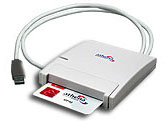
"Door/Gate Activation Port" is the RS-232 port
for communicating with the relay control device. (When you install
the USB-to-RS232 adapter, Windows will automatically assign a RS-232 port
to the device. This is the port to use.)
"Door/Gate On Delay" defines the amount of time
do delay when the door/gate relay is activated due to valid card insertion.
After this time period elapses, the relay de-actviates automatically.
"Door/Gate On Cmd" and "Door/Gate Off Cmd" define
the command strings that are used for activating and de-activating the
door/gate relay. You should not modify these strings unless instructed
to do so by Kadtronix.
SCAS application software allows you to record
all access attempts to daily log files. To enable this feature, check
the "Write to log file" check-box. In addition, you may wish to hear
a computer-generated sound when a card is inserted in any reader.
To enable this feature, check the "Play sound on card insertion" check-box.
Use the "Browse" button to select the desired sound (.wav) file.
Use the "Preview" button to hear the sound.
Use "Increment card access counter" to automatically increment the card's
internal counter on each access entry. If checked, the counter will
be compared with the maximum value. If the counter reaches this maximum,
access will be denied.
(Note: While this feature can be quite
useful, you should know that the additional processing involved introduces
a delay between the time of card-insertion and door/gate activation.
The additional delay is approximately one second.)
When you have completed all property settings and are satisfied, click
"OK" to terminate the dialog and save your new settings. If you do
not wish to save your settings, click "Cancel" instead.
-
View / Modify Card Contents
The main display provides a real-time view of the card inserted in
any of the available card-readers. Use the "Select" combo-box control
to choose the desired reader. Ordinarily, all fields will be blank,
indicating there is no inserted card. When a card is inserted,
its contents will be populated in the fields. When the card is
removed, the fields will be cleared.
As administrator, you may freely modify the contents of any inserted
card. A card customer is assigned a number of fields as shown above.
The name fields should contain the customer's first and last name.
The ID is optional and should be any desired combination of alpha-numeric
characters. (Note: You may choose to
use strictly numeric characters as shown in the example above. Choosing
a numeric ID allows SCAS to automatically increment the value after each
assignment.)
"No. Access Entries" defines the number of accesses which have occurred
by this customer. On each card-insertion, this value is automatically
incremented if the "Increment card access counter" check-box is enabled
(see the Properties page).
"Max. Access Entries" is the maximum allowed entries for this customer.
When "No. Access Entries" reaches this value, the customer will be denied
access.
"Termination Date" serves a similar purpose as "Max. Access Entries".
The customer will be allowed access as long as the current date precedes
the termination date. Otherwise the customer is denied access.
(Note: Both the termination date and max. access entries are used
concurrently to determine a customer's access. If either condition
is met, customer access is denied.)
"Date Created" indicates the date which the card was formatted (or re-formatted)
for customer use.
"Last Modified" defines the date which the card contents were last changed
or updated.
"Door/Gate Activation" defines the RS-232 communication port for relay
control. (This is the same information indicated in the Properties
page described previously.) The "..." button to the right of the
combo-box control is a test button. When pressed, this button issues
a relay "ON" command to activate your door or gate. It then de-activates
automatically after a pre-determined time period. You may also use
this feature to open a door/gate for non-card holding visitors.
There are a number of buttons near the bottom of the display which you
will find useful as the administrator.
The "Format..." button prepares a card for first-time use and permits
you to assign the card to a customer.
"Erase..." removes all content from a card, making it invalid.
An erased card behaves like a card which has never been formatted.
Any access attempt using an erased card will be denied by SCAS.
Use the "Apply..." button to store any field changes you have made to
a card. You, the administrator, may modify any of the card fields
as desired.
The "Refresh" button udpates the display with the current card contents.
-
Reader Status
This region of the display provides a quick summary of attached readers
and their operational status.
As indicated above, all defined readers are listed in the region.
The check-box indicates whether access control is
enabled for the designated reader. (This is the same designation
described in the Properties page.)
The colored LED indicators define the connection
and card-insertion state of each reader. A LED that is off (dark
appearance) indicates a non-detected reader, typically meaning that the
reader is not plugged into the computer. A solid green indicator
means the card-reader is detected and active and there is no inserted card.
A flashing green indicator defines a detected card-reader that has an inserted
card.
Summary text near the bottom of the region provides
information concerning the number of active readers detected by SCAS software:
"Detected card-readers:
3"