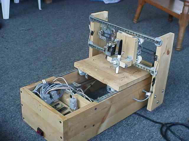
 PCB Plotter (prototype)
 | Description | 3-axis PCB plotter |
| Processor | Intel 8749 Micro |
| 2 Motors | 4-Phase Steppers |
| Power | 12V/5V Dual-Voltage Power Supply |
| 4 Limit sensors | 2 X-axis, 2 Y-axis |
| Digital Signals | 1 Output, 1 Input |
| Date Created | August 1993 |
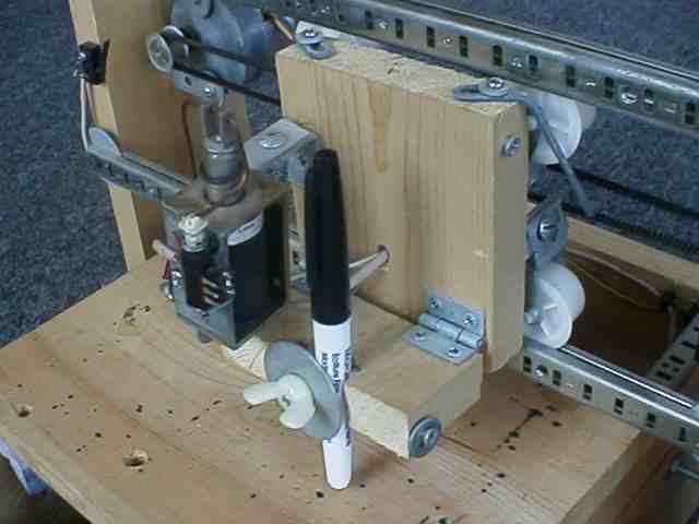
The plotter has 2 moving platforms
platforms,
each of which has a set of 4 large nylon rollers which ride on metal
tracks.
The large, horizontal platform functions as a table on which a circuit
board is placed. The smaller, vertically mounted platform
provides
support and mounting for the pen actuator.
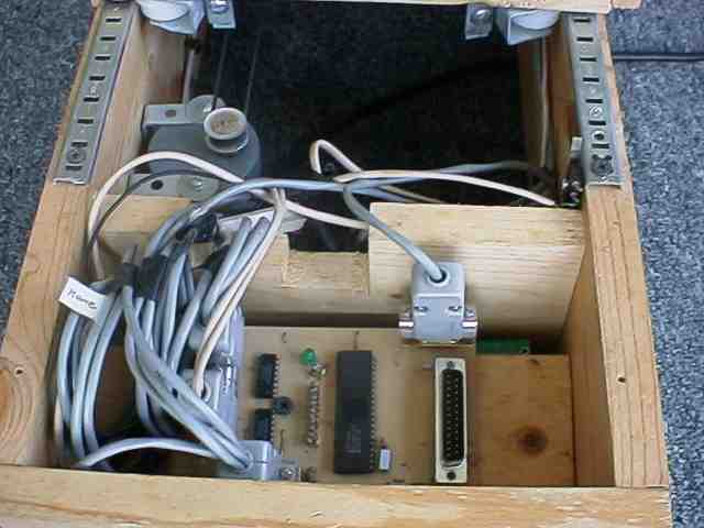
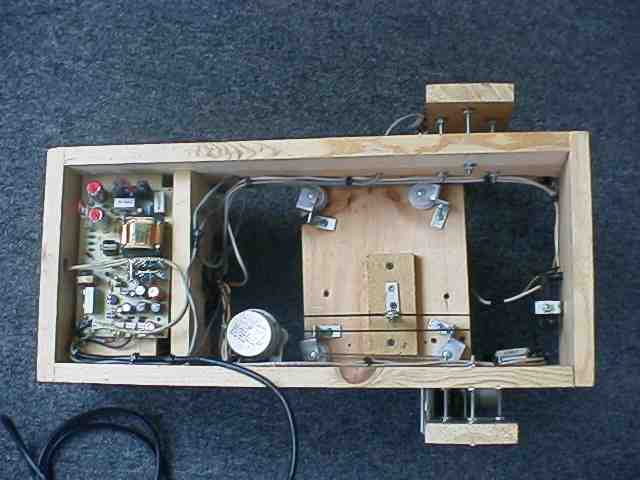 Underside view |
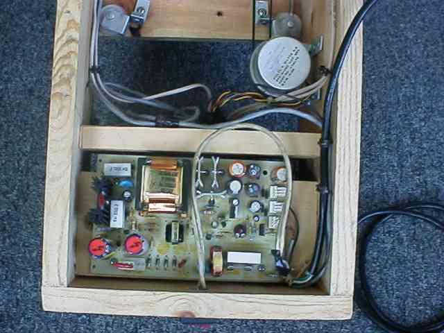 Underside view, power supply |
The plotter is controlled by a
custom-designed
intelligent STPC-10 stepper controller. This controller provides
simulatneous control of 2 stepper motors. It also provides +/-
inputs
for limit sensor switches which automatically shut off a motor when the
limit is actuated. Also provided is 1 digital input and 1 digital
output. The application of these signals is
user-specifiable.
For the purpose of the plotter, the digital output is used to control
the
solenoid pen actuator. The digital input confirms the position of
the pen, up or down.
The host software was also
custom-developed,
written in C. This software contains a simple GUI for designing a
circuit using pads and traces. Once the circuit has been
designed,
the user prepares a bare copper-clad board, loads a marker pen, and
starts
the plotter. Once the plot has completed, the board is
ready
to be etched and drilled.